💻 Vertex colors
This exercise uses a file exported from the ParaView scientific visualization package, and uses some of the workflow needed to get it into Blender.
X3D Importer
Check if you have a menu option to import X3D format. For this,
go to File -> Import and check if there is an entry X3D Extensible 3D (.x3d/.wrl).
If you do NOT have the X3D import option then perform the following steps to enable the X3D add-on (otherwise continue to step 3):
- Open the preferences window with
Edit -> Preferences - Switch to the
Add-onstab - In the search field (with the little spyglass) enter "X3D", the list should get reduced to just one entry
- Enable the checkbox left of "Import-Export: Web3D X3D/VRML2 format"
- Close the preferences window (it saves the settings automatically)
- Under
File -> Importthere should now be a new entryX3D Extensible 3D (.x3d/.wrl)
-
Importing data always adds to the current scene. So start with an empty scene, i.e. delete all objects.
-
Make sure Blender is set to use
Cyclesas the renderer. For this, switch to the Render tab in the properties area.
Check the
in the properties area.
Check the Render Enginedrop-down, it should be set toCycles. -
Import file
glyphs.x3dusingFile > Import > X3D Extensible 3D, using the importer settings (on the right side of the window when selecting the file to import):Forward: Y Forward,Up: Z Up. The latter will make sure the imported model is oriented correctly. -
This X3D file holds a scene exported from ParaView. Check out the objects in the scene to get some idea of what it contains.
-
Delete all the lights in the scene to clear everything up a bit. Add a single sun light in return.
Inspecting the vertex colors
This 3D model has so-called "vertex colors". This means that each vertex of the geometry has an associated RGB color, which is a common way to show data values in a (scientific) visualization.
There are a few ways to inspect if, and what, vertex colors a model has. First, there is the so-called Vertex Paint mode. In this mode vertex colors are shown when they are available and can even be edited ("painted").
To enable Vertex Paint mode:
- Select the 3D arrows in the scene (as the only single selected object)
- Open the Mode pie menu with
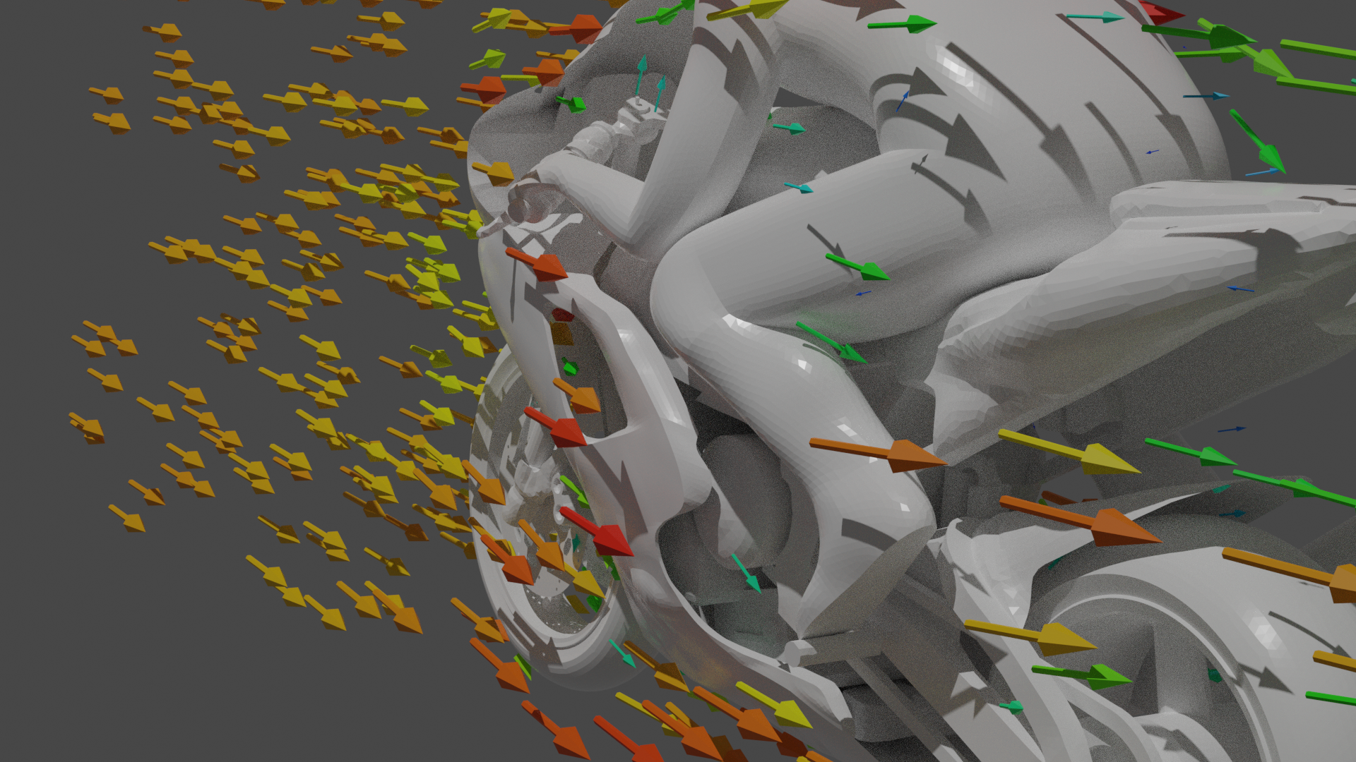
Ctrl-TABand switch toVertex Paint. An alternative is to use the menu showingObject Modein the upper-left of the 3D view header and selectVertex Paintthere. - The 3D View should now show the arrow geometry colored by its vertex colors. The colors shown are velocity values from a computational flow simulation, using the well-known rainbow color scale (low-to-high value range: blue → green → yellow → orange → red)
Altering vertex colors
You might have noticed two things have changed in the interface: 1) the cursor is now a circle, and 2) the tool shelf on the left now shows color operations (paint brush = Draw, drop = Blur, ...)
As this is Vertex Paint mode you can actually alter the vertex colors. This works quite similar to a normal paint program, like Photoshop or the GIMP, but in 3D. Although it may not make much sense to change colors that are based on simulation output (like these CFD results) it can still be interesting to clean up or highlight vertex-colored geometry in certain situations.
- Experiment with vertex painting: move the cursor over part of the arrow geometry, press and hold
LMBand move the mouse. See what happens. - Switch to the Tool settings
 tab in the properties area on the right-hand side of the window
 - You can change the color you're painting with with the colored box directly right of the
Drawin the bar at the top of the 3D view area (it's also shown and editable in the bar at the top of the 3D view). Click the color to bring up the color chooser. You can also change the radius and strength settings to influence the vertex painting. - Change back to
Object Modeusing theCtrl-TABmode menu when you're done playing around. Note that the arrows no longer show the vertex colors.
Rendering
The second way to use vertex colors is to apply them during rendering.
- If you've screwed up the vertex colors really badly in the previous steps you might want to reimport the model...
- Make the 3D arrows in the scene the single selected object
- Switch to the
Object Data tab in the properties
 - Check that there is an entry "Col" in the list under
Color Attributes. A model can have multiple sets of vertex colors, but this file has only one set called "Col", which has domainFace Cornerand typeByte Color.
Now we will set up a material using the vertex colors stored in the "Col" layer.
- Go to the Material tab

- Select the material called "Material" in the drop-down list left of the New button. This set the (grey) material "Material" on the arrows geometry.
- Press
F12(or use interactive render) to get a rendered view of the current scene.
You'll notice that all the geometry is grey/white, i.e. no vertex colors are used. We'll now alter the material to use vertex colors.
- In the settings of the material there is a field called "Base Color" with a white area right of it. This setting controls the color of the geometry.
- Click the button left of the color area (it has a small yellow circle in it)
- Pick
Attributefrom the left-most column labeledInput. This specifies that the material color should be based on an attribute value. - Base Color is now set to
Attribute | Color. Directly below the entry there is aNamefield. Pick "Col" from the list. This specifies that the attribute to use is called "Col" and comes from the mesh geometry (i.e. our vertex colors). - Now render the scene again
- The rendered image should now be showing the arrow geometry colored by vertex colors